

Digital Fault Recording (DFR) systems capture high-speed electrical data during faults and disturbances. For Australian EPCs, the right system should provide sufficient sampling and channel capacity, accurate time synchronisation, flexible triggering, open data formats, reliable communications and integration with the wider substation monitoring architecture. These requirements affect fault investigation, commissioning, asset management and long-term network operations.
What should a DFR system capture?
A DFR should capture enough electrical and digital information to reconstruct what happened before, during and after a fault. This normally includes voltage and current waveforms, digital status signals, protection operations and other relevant measurements. The required channel configuration should be established during the engineering and protection design stage.
For an EPC, the first question is not simply how many channels the recorder has. It is which signals need to be recorded to answer the likely engineering questions after an event.
For example, a substation DFR may need to capture:
- Three-phase voltage and current
- Neutral or residual quantities
- Circuit-breaker status
- Protection relay trip outputs
- Recloser or switching signals
- Transformer or generator-related measurements
- Other digital indications relevant to the protection scheme
The channel requirement should therefore follow the protection and control philosophy rather than being selected independently.
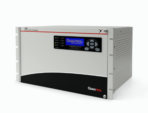
Insulect's Qualitrol IDM+ is available in configurations with 9, 18 or 36 analogue channels, alongside digital inputs, allowing the recording architecture to be matched to the application.
How fast should a digital fault recorder sample?
A DFR should sample fast enough to capture the transient behaviour relevant to the fault investigation. EPCs should consider the fastest phenomenon they need to analyse, the system frequency, record duration and storage requirements rather than selecting a sampling rate based on a single specification.
Sampling rate determines how much detail a recorder can capture from rapidly changing electrical signals.
Insulect's Qualitrol IDM+ supports sampling rates up to 512 samples per cycle. On a 50 Hz system, this corresponds to 25.6 kHz. The available sampling rates can also be reduced for applications where lower-speed recording is appropriate.
This distinction matters in practice.
A slow recording may be adequate for analysing longer-duration changes in voltage or power. A high-speed DFR record is more useful when engineers need to examine the waveform during a short-duration fault, switching event or transient.
EPCs should therefore specify the required sampling rate alongside the type of events the system must capture.
Does a DFR need time synchronisation?
A DFR should provide accurate time synchronisation when records from multiple devices or substations need to be compared. Time alignment allows engineers to establish the sequence of events and correlate measurements from different locations, protection devices and monitoring systems.
This becomes particularly important during network events involving multiple substations.
For example, a fault may cause a protection relay to operate at one location while voltage and current changes are detected at another. If the records do not share a reliable time reference, engineers may struggle to determine the order of events.
The Qualitrol IDM+ supports GPS and IRIG-B time synchronisation, with the Insulect specification identifying accuracy down to 100 nanoseconds for the relevant configuration.
For an EPC, the specification should therefore address:
- Time source
- Synchronisation method
- Required accuracy
- Time distribution across devices
- Behaviour if the primary time source is unavailable
The requirement should also be considered alongside the wider substation automation architecture.
Should a DFR support COMTRADE?
A DFR should support COMTRADE when EPCs need to exchange fault records between different manufacturers' equipment and analysis applications. IEC 60255-24:2013 defines a common format for transient waveform and event data from power systems, supporting the exchange of fault, test and simulation data.
IEC 60255-24:2013, also known as IEEE C37.111-2013, defines the COMTRADE format for transient waveform and event data. IEC describes the standard as a common format for exchanging different types of fault, test and simulation data.
This matters because EPC projects often combine equipment from several manufacturers.
Consider a new substation where protection relays, DFRs, power quality monitors and control systems come from different suppliers. If the fault recorder stores information only in a proprietary format, engineers may need vendor-specific software to analyse the event.
A common data format reduces that dependency and makes it easier to move records between engineering and analysis tools.
EPC specifications should therefore state the required data format rather than simply asking for "fault recording capability."
How should a DFR integrate with IEC 61850 systems?
A DFR should fit the project's substation automation architecture and communications requirements. Where IEC 61850 is specified, EPCs should confirm which IEC 61850 services, data models and interfaces the recorder supports rather than treating IEC 61850 as a simple communications checkbox.
IEC 61850 covers communication networks and systems for power utility automation. IEC 61850-7-3, for example, defines common data classes used in the description of device models and functions for substations and feeder equipment.
The wider IEC 61850 framework also addresses substation automation, including communication between intelligent electronic devices and substation controllers.
For an EPC, the practical question is how the DFR will fit into the project's actual architecture.
This may include:
- Ethernet connectivity
- IEC 61850 integration
- Network time synchronisation
- Data access from a central system
- Trigger sharing between monitoring devices
- Integration with station-level monitoring software
The project specification should identify the required interfaces and functions rather than relying on a generic statement that a device is "IEC 61850 compatible."
What trigger functions should a DFR have?
A DFR should provide flexible event triggers so the recorder captures the conditions that matter to the investigation. EPCs should consider threshold, rate-of-change, digital-input and system-event triggers, together with sufficient pre- and post-event recording.
A fault record is more useful when it shows what happened immediately before the fault as well as the fault itself.
For example, an EPC investigating a circuit-breaker operation may need to see:
- The electrical conditions before the operation
- The protection signal
- The breaker command
- The change in current and voltage
- The breaker status
- The system response after the event
The Qualitrol IDM+ supports multiple trigger types and can record data before and after an event. Insulect's published specification identifies up to 30 seconds of pre- and post-event data depending on configuration.
The appropriate record duration should be established from the application rather than assuming that longer is always better.
How much storage does a DFR need?
A DFR needs enough storage for the expected number, duration and size of event records without creating unnecessary data-management requirements. EPCs should consider analogue channels, digital channels, sampling rate, record length, event frequency and the project's data-retention requirements when specifying storage.
Storage requirements can change significantly between a small substation and a large generation facility.
A recorder capturing 36 analogue channels at high speed will generate substantially more data than a small recorder monitoring a limited number of signals.
The Qualitrol IDM+ supports 4 GB of standard storage, with larger storage options available depending on configuration.
EPCs should also consider how records are transferred from the device and where long-term records will be stored. A large local storage capacity does not replace the need for an appropriate data-management strategy.
What communications should a DFR support?
A DFR should provide communications that match the project's network architecture and operational requirements. EPCs should consider Ethernet, fibre, serial or other required interfaces, together with the protocols needed to transfer records, alarms and operational data to monitoring or control systems.
The communications requirement should be defined early because it can affect network design, equipment selection and commissioning.
Insulect's IDM+ documentation identifies Ethernet, fibre, modem and serial communication options, while the platform can be integrated with centralised iQ+ software for data collection, storage, processing and visualisation.
For an EPC, the important question is not simply whether the recorder has an Ethernet port. The specification should establish what information needs to move, where it needs to go and how the receiving system will use it.
How should DFR data be managed after a fault?
A DFR should form part of an event-analysis workflow rather than operate as an isolated data-storage device. EPCs should consider how records are automatically collected, stored, visualised, analysed and shared with the engineers responsible for protection, commissioning and asset management.
This is where the difference between a recorder and a monitoring system becomes important.
A recorder may successfully capture an event, but engineers still need to find the record, identify the relevant channels, compare it with other records and determine what happened.
Insulect's iQ+ Master Station Software automatically polls connected devices, downloads event data and stores it in a central database. It can also support analysis and visualisation of digital fault records alongside other monitoring data.
For a multi-substation project, centralised data management can reduce the time engineers spend manually collecting records from individual devices.
What should EPCs consider for Australian substations?
EPCs should specify the DFR as part of the complete high-voltage installation and protection system rather than treating it as a standalone monitoring device. The design should align with the project's applicable Australian requirements, network-operator specifications, protection philosophy, communications architecture and commissioning requirements.
AS 2067:2016, Substations and high voltage installations exceeding 1 kV a.c., provides common rules for the design and construction of electrical power installations above 1 kV AC. Standards Australia describes it as a fundamental standard for Australian high-voltage installations.
AS 2067 is not a DFR-specific standard. Its relevance is the broader installation context in which the monitoring and protection equipment is deployed.
EPCs should also check the requirements of the relevant network operator, project owner, protection specification and applicable regulatory framework. Standards Australia notes that Australian Standards can become mandatory where legislation or regulatory requirements reference them.
This is particularly important for projects involving transmission connections, generation, BESS and other grid-connected assets where project-specific technical requirements may sit alongside Australian and international standards.
How does a DFR help with maintenance decisions?
A DFR helps maintenance teams distinguish between an isolated electrical event and a developing equipment problem by providing evidence of what the power system and connected equipment experienced. Engineers can use event records to support decisions about inspection, testing, protection review and equipment condition assessment.
For example, repeated fault records may reveal that a circuit breaker, transformer or feeder is repeatedly exposed to particular electrical conditions.
Instead of relying only on a maintenance schedule, engineers can investigate the actual electrical behaviour associated with the event.
DFR records can also support post-fault investigations by helping engineers determine whether protection operated as expected and whether the equipment response matched the intended protection scheme.
This can influence decisions such as whether equipment requires inspection, whether protection settings need review, or whether additional monitoring is warranted.
What should EPCs include in a DFR specification?
EPCs should specify the DFR around the project's required measurements, event types, interfaces and operational workflow. A useful specification should address channels, sampling, triggering, time synchronisation, data format, communications, storage, environmental requirements, integration and testing rather than simply naming a digital fault recorder.
A practical EPC specification checklist could include:
| Requirement | What to define |
|---|---|
| Analogue inputs | Number, voltage/current configuration and accuracy |
| Digital inputs | Required status and protection signals |
| Sampling | Required sampling rate and selectable rates |
| Triggering | Threshold, digital, rate-of-change and other required triggers |
| Record length | Pre-event and post-event duration |
| Time synchronisation | GPS, IRIG-B or project-specific requirement |
| Data format | COMTRADE and other required formats |
| Communications | Ethernet, fibre, serial and required protocols |
| Storage | Local capacity and data-retention requirements |
| Central software | Data collection, analysis and visualisation |
| Integration | IEC 61850 and other project interfaces |
| Testing | FAT, SAT, commissioning and record-verification requirements |
The final specification should always be checked against the project owner's technical requirements and applicable network-operator standards.
Which Insulect solution can support digital fault recording?
Insulect supplies Qualitrol Digital Fault Recording solutions for high-voltage substations, transmission systems and generating stations. The IDM+ can combine DFR with other monitoring functions, including Dynamic Disturbance Recording, Power Quality Monitoring, Phasor Measurement and other functions depending on configuration.
For projects that require more than fault waveform capture, this multifunction approach can reduce the need to specify separate monitoring devices for every application.
Insulect also supplies iQ+ Master Station Software, which provides centralised collection, storage, processing and visualisation across supported monitoring devices.
The appropriate configuration depends on the project's electrical system, protection philosophy, monitoring requirements and communications architecture.
Frequently Asked Questions
Sources and Standards
- IEC 60255-24:2013, Measuring relays and protection equipment – Part 24: Common format for transient data exchange (COMTRADE) for power systems. IEC identifies this as the standard for exchanging transient waveform and event data.
- IEEE/IEC C37.111-2013, Common Format for Transient Data Exchange (COMTRADE) for Power Systems. IEEE identifies C37.111-2013 as the corresponding IEEE/IEC standard.
- IEEE C37.2-2022, IEEE Standard for Electrical Power System Device Function Numbers, Acronyms, and Contact Designations. The standard includes the Digital Fault Recorder function designation.
- IEC 61850-7-3:2010+A1:2020, Communication networks and systems for power utility automation – Part 7-3: Basic communication structure – Common data classes.
- AS 2067:2016, Substations and high voltage installations exceeding 1 kV a.c. Standards Australia identifies the standard as providing common rules for the design and construction of high-voltage electrical power installations.
- Qualitrol IDM+ / Insulect DFR technical documentation, including channel configurations, sampling, triggering, time synchronisation and communications specifications.
Talk to Insulect About Your DFR Requirements
Planning a new substation, generation project or network upgrade? Insulect can help you assess DFR requirements, monitoring architecture and equipment configuration for your application.
Contact Insulect to discuss your project requirements.