

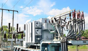
Partial discharge (PD) in high-voltage equipment is caused by localised electrical breakdown within or around an insulation system, when the local electric field becomes strong enough to break down a small region of the insulating material. It can develop due to manufacturing defects, insulation ageing, contamination, moisture, poor installation or excessive electrical stress. If left undetected, repeated partial discharge activity can progressively deteriorate insulation and increase the risk of equipment failure.
Partial discharge can occur in a wide range of high-voltage assets, including transformers, switchgear, power cables, cable terminations, bushings, motors and generators.
Detecting PD early is important because it provides an indication of potential insulation problems before they develop into more serious faults. Electrical, electromagnetic and acoustic monitoring technologies allow engineers to identify, assess and locate partial discharge activity, supporting more informed maintenance decisions and improved asset reliability.
What Is Partial Discharge and Why Does It Occur?
Partial discharge is an electrical discharge that only partially bridges the insulation between conductors. Unlike a complete electrical breakdown, it does not initially create a continuous conductive path between two electrodes.
It typically occurs at localised weak points in an insulation system, such as air-filled voids, cracks, contaminated surfaces or areas where electrical field stress is concentrated.
When the local electric field exceeds the dielectric strength of the surrounding medium, a discharge occurs. Although each individual event may involve a relatively small amount of energy, repeated activity can gradually damage the surrounding insulation.
Over time, this deterioration can contribute to insulation breakdown, equipment failure and unplanned outages.
What Are the Main Types of Partial Discharge?
Partial discharge is generally classified according to where it occurs and the mechanism involved.
1. Internal partial discharge
Internal PD occurs within cavities or voids in solid or liquid insulation.
These defects can develop during manufacturing or as insulation deteriorates over time. The electrical field can become concentrated within the void, causing the gas inside it to break down repeatedly.
Internal PD is particularly relevant to:
- Cast-resin transformers
- Cable insulation
- Epoxy-insulated switchgear
- Bushings and other solid-insulated components
2. Surface partial discharge
Surface PD occurs along the boundary between insulating materials or across an insulating surface.
It can develop when electrical stress becomes concentrated around insulation interfaces, particularly where there is contamination, moisture, surface damage or inadequate electrical field grading.
It may affect:
- Insulator surfaces
- Cable terminations
- Transformer bushings
- Switchgear insulation components
3. Corona discharge
Corona is a form of partial discharge that occurs in the gas surrounding an energised conductor when the local electric field becomes strong enough to ionise the surrounding gas.
It is commonly associated with sharp conductor edges, poorly designed electrical connections, damaged insulation or inadequate clearances.
Corona may produce audible noise, ozone and ultraviolet emissions. It can also contribute to gradual deterioration of nearby insulating materials.
What Causes Partial Discharge in High-Voltage Equipment?
Several factors can contribute to partial discharge. Understanding the underlying causes helps engineers identify vulnerable components and select appropriate monitoring and maintenance strategies.
1. Manufacturing Defects and Insulation Voids
Manufacturing defects are one potential source of internal partial discharge.
During the production of solid insulation components, small air pockets, voids or imperfections may remain within the material. These defects create areas where the dielectric properties differ from the surrounding insulation.
When high voltage is applied, the local electrical field can become concentrated within these cavities, triggering repeated discharge activity.
Practical example:
A cast-resin transformer may contain small voids within its epoxy insulation. Under normal operating voltage, these voids can experience localised electrical stress, resulting in internal partial discharge.
If the activity continues, the surrounding insulation may gradually deteriorate, increasing the risk of insulation failure.
2. Insulation Ageing and Deterioration
Electrical insulation deteriorates over time due to a combination of electrical, thermal, mechanical and environmental stresses.
Ageing can result in:
- Cracks or delamination in solid insulation
- Deterioration of insulating materials
- Changes in dielectric properties
- Increased surface contamination
- Degradation of insulation interfaces
As insulation condition changes, local electric field distribution can become less uniform, creating conditions that may initiate or increase partial discharge activity.
Practical example:
An ageing power cable may develop insulation deterioration around a joint or termination. If the electrical field becomes concentrated around the affected area, partial discharge may develop and progressively damage the insulation.
PD testing can help identify the affected section and support decisions about further investigation, repair or replacement.
3. Moisture and Contamination
Moisture and contamination can affect the dielectric properties and electrical performance of insulation systems.
Water ingress, dust, conductive particles, oil contamination and other foreign materials can create localised electrical field concentrations or reduce surface insulation performance.
These conditions can increase the likelihood of surface discharge or other forms of insulation deterioration.
Practical example:
Moisture or contamination on an outdoor insulator can affect its surface insulation performance, particularly under humid or polluted environmental conditions.
Regular inspection, appropriate cleaning and condition monitoring can help identify deterioration and reduce the risk of insulation-related problems.
4. Electrical Overstress and Poor Field Distribution
High electrical stress can contribute to partial discharge, particularly where the electric field is not distributed evenly.
Potential contributing factors include:
- Overvoltage conditions
- Switching transients
- Inadequate electrical clearances
- Sharp conductor edges
- Poorly designed insulation interfaces
- Defective stress-control components
Areas with concentrated electrical stress are more vulnerable to localised insulation breakdown.
Practical example:
An incorrectly installed cable termination may have inadequate stress control, causing an uneven electric field distribution around the termination.
This can initiate surface or internal discharge activity, potentially leading to progressive insulation deterioration.
5. Poor Installation and Maintenance
Installation quality plays an important role in the long-term performance of high-voltage insulation systems.
Incorrect cable jointing, damaged insulation, loose connections, inadequate clearances and improper assembly can introduce defects that create conditions for partial discharge.
For example, an incorrectly assembled cable joint may contain air pockets or insulation interfaces that experience elevated electrical stress.
Testing after installation and during commissioning can help identify certain insulation defects before equipment enters normal service.
How Can Partial Discharge Be Detected?
Partial discharge produces measurable electrical and physical signals, including current pulses, electromagnetic emissions, acoustic signals and, in some cases, light and chemical by-products.
Different detection technologies capture these signals to identify and assess PD activity.
The appropriate method depends on the equipment type, operating conditions, accessibility and whether testing is performed offline or while equipment remains in service.
1. Conventional Electrical Partial Discharge Measurement
Conventional electrical PD measurement detects the electrical pulses associated with partial discharge and measures their apparent charge.
The measurement system typically includes:
- A coupling capacitor
- A measuring impedance
- A PD detector
- A calibration device
The equipment is connected to a suitable test circuit, and the measurement system detects and records discharge pulses during the applied voltage test.
Results can be analysed to assess discharge magnitude, repetition patterns and phase relationship to the applied voltage.
Where is it used?
Conventional electrical PD measurement is commonly used during factory testing, commissioning and offline diagnostic testing of high-voltage equipment.
It provides a standardised measurement approach under controlled test conditions.
2. High-Frequency Current Transformer (HFCT) Detection
High-Frequency Current Transformers (HFCTs) detect high-frequency current pulses associated with partial discharge activity.
They are commonly installed around equipment earth connections or cable screens, depending on the application.
When a discharge occurs, the resulting high-frequency signal travels through the electrical path and can be detected by the sensor.
HFCT technology is particularly useful for monitoring and investigating PD activity in installed electrical equipment.
Where is it used?
- Medium-voltage switchgear
- Power cables
- Cable joints and terminations
- Transformer earthing connections
HFCT sensors can support online monitoring, allowing engineers to investigate potential insulation issues without necessarily taking equipment out of service.
3. Ultra-High-Frequency (UHF) Detection
UHF detection identifies electromagnetic signals generated by partial discharge events.
When PD occurs, it produces electromagnetic emissions across a broad frequency range. UHF sensors capture signals within the ultra-high-frequency range, which can be analysed to identify discharge activity.
UHF technology is particularly useful in gas-insulated switchgear (GIS), where electromagnetic signals can be detected using appropriately installed sensors.
Where is it used?
- Gas-insulated switchgear
- Gas-insulated substations
- Selected high-voltage enclosures and equipment
UHF detection can help identify PD activity within enclosed equipment and, where suitable sensor arrangements are available, support the localisation of discharge sources.
4. Acoustic Detection
Partial discharge produces small pressure waves that can travel through surrounding insulation materials, oil or equipment enclosures.
Acoustic sensors detect these signals and can help identify the location of discharge activity.
For oil-filled transformers, acoustic sensors may be attached to the transformer tank to detect signals associated with internal PD.
Where is it used?
- Oil-filled power transformers
- Gas-insulated switchgear
- Enclosed high-voltage equipment
Acoustic detection can complement electrical monitoring, particularly when engineers need to investigate the potential location of an internal discharge source.
5. Visual and Ultraviolet Detection
Some forms of partial discharge, particularly corona, produce visible or ultraviolet emissions.
Specialist cameras can detect ultraviolet emissions that may not be visible to the naked eye.
Visual inspection may also identify signs associated with external discharge, such as surface deterioration or deposits around affected components.
Where is it used?
- Outdoor substations
- Overhead electrical equipment
- Insulators and conductor connections
- Air-insulated switchgear
UV detection can help identify corona activity and potential problem areas without direct electrical contact with the equipment.
Comparison of Partial Discharge Detection Methods
| Detection method | What it detects | Typical applications |
|---|---|---|
| Conventional electrical measurement | Apparent charge from PD pulses | Factory testing, commissioning and offline testing |
| HFCT | High-frequency current pulses | Cables, switchgear and earth connections |
| UHF | Electromagnetic emissions | GIS and enclosed HV equipment |
| Acoustic | Pressure waves generated by discharge activity | Transformers and enclosed equipment |
| UV detection | Ultraviolet emissions | Outdoor substations and corona detection |
No single detection method is suitable for every application. In some cases, combining multiple technologies provides a more complete understanding of PD activity.
What Is the Difference Between Online and Offline Partial Discharge Testing?
Partial discharge testing can be performed online or offline, depending on the equipment and diagnostic objectives.
Online Partial Discharge Monitoring
Online monitoring detects PD activity while electrical equipment remains energised and in service.
Sensors are installed at suitable locations to continuously or periodically collect signals associated with discharge activity.
Advantages include:
- Monitoring equipment under actual operating conditions
- Identifying changes in PD activity over time
- Reducing the need for equipment shutdown solely for monitoring
- Supporting early identification of developing insulation problems
- Providing information for condition-based maintenance
Online monitoring is particularly valuable for critical assets where unplanned outages can have significant operational consequences.
However, background electrical noise and interference can affect measurements. Appropriate sensor selection, signal processing and expert interpretation are important.
Offline Partial Discharge Testing
Offline testing is performed when equipment is de-energised and isolated from normal operation.
A separate test voltage is applied to the equipment, allowing engineers to assess insulation performance under controlled conditions.
Advantages include:
- Controlled testing conditions
- Established measurement procedures
- Detailed diagnostic assessment
- Suitability for factory acceptance and commissioning tests
However, offline testing requires equipment to be taken out of service and may not reproduce exactly the same electrical and environmental conditions experienced during normal operation.
Which Approach Should You Choose?
Online and offline testing serve different purposes and should not necessarily be treated as alternatives.
For critical equipment, online monitoring can provide ongoing visibility of insulation condition, while offline testing can provide more detailed diagnostic information when required.
The appropriate approach depends on equipment criticality, operating conditions, accessibility, risk and maintenance objectives.
How Does Partial Discharge Monitoring Support Equipment Reliability?
Partial discharge monitoring provides information about insulation condition that may not be available through routine visual inspections or conventional maintenance activities.
Its value extends beyond simply identifying whether discharge activity is present. Monitoring trends and understanding the characteristics of PD signals can help engineers make more informed maintenance decisions.
Early Identification of Insulation Problems
Increasing or changing PD activity can indicate developing insulation defects.
Monitoring allows engineers to investigate abnormal conditions before they progress further.
Better Maintenance Planning
Instead of relying entirely on fixed maintenance intervals, asset owners can use PD monitoring information to help prioritise inspections, diagnostic testing and maintenance activities.
Reduced Risk of Unexpected Outages
Identifying and investigating developing insulation issues can help reduce the risk of unexpected equipment failures and associated network disruptions.
Improved Asset Condition Visibility
Historical PD measurements provide a reference for understanding how insulation condition changes over time.
This information can support asset health assessments and longer-term maintenance planning.
It is important to recognise that not every PD indication represents an immediate failure risk. Results must be interpreted in context, considering equipment design, operating conditions, background noise and other diagnostic information.
What Standards Guide Partial Discharge Testing and Measurement?
Several international standards provide guidance on partial discharge measurement, detection technologies and equipment-specific testing.
The following standards are particularly relevant.
| Standard | Scope and relevance |
|---|---|
| IEC 60270:2025 | Defines charge-based measurement methods, measuring circuits, calibration and test procedures for partial discharge under AC and DC test voltages. |
| IEC TS 62478:2016 | Covers electromagnetic (HF, VHF and UHF) and acoustic methods for measuring and locating partial discharge. |
| IEEE C57.113-2023 | Provides recommended practices for measuring partial discharge in liquid-filled power transformers and shunt reactors. |
| IEEE C57.160-2023 | Provides guidance on electrical measurement of partial discharge in high-voltage bushings and instrument transformers. |
| IEEE 400.3-2022 | Covers field diagnostic testing of installed shielded power cable systems using electrical partial discharge detection, measurement and location. |
Understanding the Standards
IEC 60270:2025 – Charge-Based Measurement of Partial Discharges
This standard provides the recognised framework for conventional electrical PD measurement.
It covers measurement quantities, test circuits, calibration requirements, measurement procedures and methods for distinguishing PD signals from external interference.
IEC TS 62478:2016 – Electromagnetic and Acoustic Methods
This technical specification addresses alternative detection methods, including HF, VHF, UHF and acoustic measurements.
It also considers sensor applications, PD location and measurement system sensitivity.
IEEE C57.113-2023 – Liquid-Filled Transformers and Shunt Reactors
This recommended practice covers wideband measurement of apparent charge associated with PD during AC testing of liquid-filled power transformers and shunt reactors.
IEEE C57.160-2023 – Bushings and Instrument Transformers
This guide addresses electrical PD measurement in high-voltage bushings and instrument transformers under AC and DC test voltages.
IEEE 400.3-2022 – Shielded Power Cable Systems
This guide covers field diagnostic testing of new and service-aged installed shielded power cable systems, including cables, joints and terminations, using electrical PD detection, measurement and location.
These standards address different applications and measurement methods. Engineers should select the relevant standard according to the equipment being tested and the purpose of the assessment.
How Insulect Supports Partial Discharge Monitoring
Detecting partial discharge is an important part of understanding insulation condition and managing the reliability of high-voltage electrical assets.
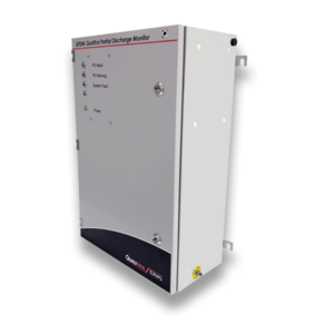
Insulect supplies partial discharge monitoring and diagnostic solutions from established technology partners, including Qualitrol, supporting utilities and industrial operators across Australia and New Zealand.
Depending on the equipment and monitoring requirements, suitable solutions can help asset owners:
- Detect partial discharge activity in critical electrical assets.
- Monitor insulation condition and identify changes in PD activity.
- Investigate potential insulation defects.
- Support condition-based maintenance programmes.
- Make informed decisions about further testing and maintenance.
Insulect also supplies complementary transformer monitoring technologies, including dissolved gas analysis (DGA), temperature monitoring and bushing condition monitoring, helping asset owners gain a broader understanding of transformer health. Contact our team today!
For further information, explore our Partial Discharge Monitoring Solutions and Transformer Monitoring Solutions.
Frequently Asked Questions
1. Is partial discharge always a sign of insulation failure?
Not necessarily. Partial discharge indicates localised electrical activity within or around an insulation system, but its presence does not automatically mean equipment is about to fail.
The significance depends on the discharge type, magnitude, location, operating voltage, repetition pattern and how the activity changes over time.
However, persistent or increasing PD activity should be investigated because it may indicate developing insulation deterioration.
2. Can partial discharge occur in medium-voltage equipment?
Yes. Partial discharge can occur in both medium-voltage (MV) and high-voltage (HV) equipment.
It is commonly investigated in MV switchgear, power cables, cable joints, terminations and solid-insulated components.
The likelihood of PD depends on insulation design, material condition, electrical stress and the presence of defects.
3. Can partial discharge be detected while equipment is operating?
Yes. Online partial discharge monitoring allows engineers to detect and assess PD activity while equipment remains energised and in service.
Depending on the application, technologies such as HFCT, UHF and acoustic sensors can be used to monitor discharge signals without requiring equipment to be taken offline solely for testing.
4. What is the difference between partial discharge and a complete electrical breakdown?
Partial discharge is a localised electrical breakdown that only partially bridges the insulation between conductors.
A complete electrical breakdown occurs when the insulation loses its ability to withstand the applied voltage, creating a conductive path between conductors.
Repeated PD activity can contribute to insulation deterioration and increase the risk of complete breakdown.
5. Which equipment should be monitored for partial discharge?
PD monitoring can be applied to various high-voltage assets, including:
- Power transformers
- Medium- and high-voltage switchgear
- Gas-insulated switchgear (GIS)
- Power cables and cable accessories
- Transformer bushings
- Motors and generators
Monitoring priorities should be based on equipment criticality, insulation design, operating conditions and potential failure consequences.
6. How often should partial discharge testing be performed?
There is no universal testing interval for all high-voltage equipment.
Testing frequency depends on asset criticality, equipment age, operating conditions, historical test results and manufacturer recommendations.
For critical assets, continuous or periodic online monitoring may be appropriate. Additional offline testing may be required when abnormal activity is identified or as part of commissioning and maintenance programmes.
7. Can partial discharge monitoring predict when equipment will fail?
Partial discharge monitoring can identify developing insulation problems and provide valuable information about changes in equipment condition.
However, PD measurements alone cannot reliably predict an exact failure date.
Results should be assessed alongside other diagnostic information, equipment history and engineering judgement to determine the appropriate maintenance response.